Here's a couple of pictures of the underside of the turntable to show its workings.
The blue base is a piece of medium dentisty fibre board, which just happened to be painted blue.
The joist has a piece of wood cut to fit the groove and a piece of aluminium bolted to the side for the side stand.
The turntable turns on universal roller bearing houses.
The whole thing pivots on an M16 bolt which is self tapped into the wood floor.
Wednesday, 28 July 2010
Monday, 21 June 2010
Sunday, 30 May 2010
Petrol tank before repainting
Here's a few pictures of the tank before it went to the sprayers.
Looking at the underside the paint looked quite good and shiny.
Unfortunately under all the paint was a slight bit of surface rust.
So before going to the sprayers I stripped the paint as below, further after with various abrasives I got the underside gleaming like new, but I forgot to take a picture of that.
Using up the last bit of stripper I took some of the paint off the top.
The top didn't have anywhere near the amount of surface rust on it.
It then went to the spayers the next day to be given a new coat of metalic blue.
Wednesday, 5 May 2010
Air box flapper and fuel filter.
On UK bikes of this type the air box has a weighted flap on the air intake.
This helps to stop the a stutter when accelerating ( apparently ).
The rubber hinge had perished as in the photo.
A new hinge was cut and secured with stainless screws instead of rivets.
Next on the list is an essential thing for a 28year old bike is a fuel filter.
I purchased a quality filter but needed a bracket to support it due to its weight.
I'm using a stainless plate that I had from a previous bracket.
A vertical cut and a drilled hole finishes the bracket.
A small circular clampl holds the filter.
A piece of rubber pipe protects the filter glass from the clamp.
The backet in place fitted to the side of the carburetor connected with new rubber tube and pipe clips.
Monday, 19 April 2010
Engine rebuild
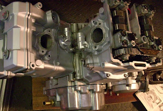
Time to put all the refurbished parts back together.
New gaskets go on under the cylinders.
Cylinders with top gaskets new seals etc, etc
The timing mark lined up to get the cam in the camchain in the correct location.
Cam chains in their correct location, I couldn't get a picture of the markings, but they're in the Haynes manual.
Finally the cam chain tensioner gets put in to get the correct tension.
Cylinders back on and all torqued down.
Intake boots with rubber gaskets instead of card ones supplied in gasket set.
Engine now ready to put back in the frame.
I have at this time got the bike back together and have started her up, just need more time spent on this blog bringing it up to date, more pictures to follow , keep tuned folks.
Tuesday, 6 April 2010
Regulator/Rectifier relocation.
With the heat build up of the R&R beside the exhaust manifold I decided to relocate it in fresh air. I used a bit of stainless plate cut and drilled to shape.
The plate with the R&R on the back of it.
The R&R bolted to the plate with stainless dome head nuts to finish it off.
The R&R and bracket in place on the bike. Its bracket is fixed on the engine mounting bolt which I remade with threads each end rather than a bolt and put domed nuts on each end.
The plate with the R&R on the back of it.
The R&R bolted to the plate with stainless dome head nuts to finish it off.
The R&R and bracket in place on the bike. Its bracket is fixed on the engine mounting bolt which I remade with threads each end rather than a bolt and put domed nuts on each end.
Monday, 5 April 2010
Oil filler, stator and Regulator/Recifier
I intend to put the fairing that came with my purchase on the bike but not all parts were included for the full adaption.
One part missing is the adaptor that replaces the oil filler cap that fits an oil tube which extends the filling to fairing bracket.
I can't find anything close on ebay so I had to find something else.
I did find a 1/2" BSP tail fitting on ebay which is a fairly standard part for hose fittings.
Only problem is the thread in the casing is metric so this was tapped out to 1/2" BSP.
The fitting as it came from ebay, fairly cheap as a used item.
The fitting screwed in place. It has now been shortened, I'll post another picture with the hose attatched when I've taken one.
The connections and sleeving on the internal engine electricals get updated next.
I bought a 3 way waterproof electrical connector off ebay for the connection between the R&R and the alternator.
The connector all fitted.
A picture of the R&R which came off the bike, soldered wires and hardened sleeving needs replacing. I found on the internet that this one comes off a Yamaha XV535, original ones tend to burn out due to the heat they produce and they are loacted in an enclosed space close to the rear exhaust manifold. I'll post another section of how I dealt with that.
The finished article with new connector and heat resistant sleeving (thanks to Mike and Chris) .
The other internal electircals also get tidied up.
Monday, 29 March 2010
Oil pump clean.
When I removing the oil pump, this is what came out of the suction tube filter gauge.
With the parts within tolerance when measured, when I was replacing the unit I noticed the bottom thread had been repaired. Unfortunately the thread insert was proud by about 1mm.
To counteract the raised insert I counterbored the oil pump housing, this lets the pump sit flat.
With the parts within tolerance when measured, when I was replacing the unit I noticed the bottom thread had been repaired. Unfortunately the thread insert was proud by about 1mm.
To counteract the raised insert I counterbored the oil pump housing, this lets the pump sit flat.
Saturday, 13 March 2010
Starter motor
The starter motor gets my attention next, on taking it apart some bits fell out.
Further inspection showed them to be the insulation on the square bolt head for the main terminal post.
The steel body gets an undercoat of zinc primer.
After removing the starter from the engine, there was a screw in a srange place.
The screw was removed and the correct one keeping part of the crankcase together was put back in place.
With seals replaced, brushed measured and within limit and a new high temperature plastic insulator in place the starter was put back together.
The starter has been sprayed all over with a high temp silver paint and screws replaced with stainless ones from ebay.
Wednesday, 24 February 2010
Starter clutch.
Here's a good example of the difference between the Haynes manual and practical advise from the Riders of Vision forum.
These starter clutches are well known to the forum members for failing due to the screws undoing. The Haynes manual says to tighten to a torque with loctite applied.
Unfortunately this is not sufficient to stop the bolts undoing.
The forum suggests getting 2mm longer bolts and riveting the ends over.
Taking my side cover off and trying the clutch mechanism seemed to work perfectly well and so I thought mine had not suffered from the loose screws.
The wiring from the stator had some bare wires showing, so I decide to get it out for repair.
The rotor had to come off and with pullers and a gentle tap it eased off. Normally these parts fly off once released but the key was a bit stiff so mine all came off quite slowly.
Now I could see the damage, the screws were just held on with one thread.
As shown in the 1st picture is the damage to the back of the rotor caused by the loose screws.
The burrs around the screw holes were ground off with a dremmel so the surface was flush.
Surprisingly only the end of the thread had been worn away, the rest of the thread was tight so I retapped the threads with an M8 solid tap.
Next picture shows the damaged bolts but luckily the cage and rollers were undamaged.
I found some M8x16 allen bolts and drilled a 3mm hole x 3mm deep.
Final picture shows the screws in place with the hole expanded with a centre punch.
Another job was to make the rotor fit correctly on the taper. A previous owner hammer the end of the rotor so it formed a ridge on the inner taper. This had the effect of the rotor clamping on the ridge and not the taper allowing it to rock slightly. This ridge was ground away with the dremmel and now has a bite to the taper when putting the parts together.
A final big thanks to the riders of Vision forum for the fix for this problem.
Tuesday, 16 February 2010
Front electrics.
I'm going to use a fairing that came with the parts I bought, unfortunately it didn't include the bracket and rubber bag that is used to put the the loom joins in. Normally they go in the headlight bucket but with the fairing the headlight sits further forward and the wires don't stretch that far. I made a plate from aluminium with 2 folds back over the fork stanchions.
The plate was drilled and tapped with cable tie bases screwed on which lined up with the various incoming looms.
The picture below shows a stainless square tube cut at an angle and drilled and tapped to hold the front plate on.
Front shot of the plate with all the cables connected.
Velcro was put on the sides and back of the aluminium plate which holds a sheet of vinyl over the top and around the sides of the plate.
Subscribe to:
Posts (Atom)