Wednesday 24 February 2010

Starter clutch.

Here's a good example of the difference between the Haynes manual and practical advise from the Riders of Vision forum.
These starter clutches are well known to the forum members for failing due to the screws undoing. The Haynes manual says to tighten to a torque with loctite applied.
Unfortunately this is not sufficient to stop the bolts undoing.
The forum suggests getting 2mm longer bolts and riveting the ends over.
Taking my side cover off and trying the clutch mechanism seemed to work perfectly well and so I thought mine had not suffered from the loose screws.
The wiring from the stator had some bare wires showing, so I decide to get it out for repair.
The rotor had to come off and with pullers and a gentle tap it eased off. Normally these parts fly off once released but the key was a bit stiff so mine all came off quite slowly.
Now I could see the damage, the screws were just held on with one thread.
As shown in the 1st picture is the damage to the back of the rotor caused by the loose screws.
The burrs around the screw holes were ground off with a dremmel so the surface was flush.
Surprisingly only the end of the thread had been worn away, the rest of the thread was tight so I retapped the threads with an M8 solid tap.


Next picture shows the damaged bolts but luckily the cage and rollers were undamaged.


I found some M8x16 allen bolts and drilled a 3mm hole x 3mm deep.

Final picture shows the screws in place with the hole expanded with a centre punch.
Another job was to make the rotor fit correctly on the taper. A previous owner hammer the end of the rotor so it formed a ridge on the inner taper. This had the effect of the rotor clamping on the ridge and not the taper allowing it to rock slightly. This ridge was ground away with the dremmel and now has a bite to the taper when putting the parts together.

A final big thanks to the riders of Vision forum for the fix for this problem.

Tuesday 16 February 2010

Front electrics.

I'm going to use a fairing that came with the parts I bought, unfortunately it didn't include the bracket and rubber bag that is used to put the the loom joins in. Normally they go in the headlight bucket but with the fairing the headlight sits further forward and the wires don't stretch that far. I made a plate from aluminium with 2 folds back over the fork stanchions.
The plate was drilled and tapped with cable tie bases screwed on which lined up with the various incoming looms.

The picture below shows a stainless square tube cut at an angle and drilled and tapped to hold the front plate on.

Front shot of the plate with all the cables connected.

Velcro was put on the sides and back of the aluminium plate which holds a sheet of vinyl over the top and around the sides of the plate.

Saturday 6 February 2010

Out with the old in with the older.

Well it had to go, I don't have space for 2 motorbikes in my shed so my loyal GS500 was sold today. I only hope the Vision will be so reliable as this bike.


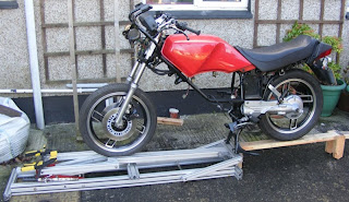
Some more pictures of my bike stand for a colleague at work who couldn't quite see how this lifted a motorbike. 1st picture shows the stand with a few modifications since the last photos. The main difference being the front wheel clamp.

The ramp is used to push the bike onto the stand, its a little higher than the stand so I can put the centre stand down without it touching down.

Now this part needs 2 people as the bike is held the lift is jacked up and starts to lift the bike on the centre stand.

The wheel is clamped and the stand lifted to its full height and then lowered onto the dowelled block so the pressure of the jack is relaxed. Lowering is then a reversal of lifting.

Simple really all you need is some extruded aluminium from a bench from work which was destined for a skip, a set of double sliding quick clamps and an old car jack which refuses to keep any jack oil in it for any length of time.
Final pictures shows how far along I am with the bike, plenty done but still plenty to do.......watch this space.....